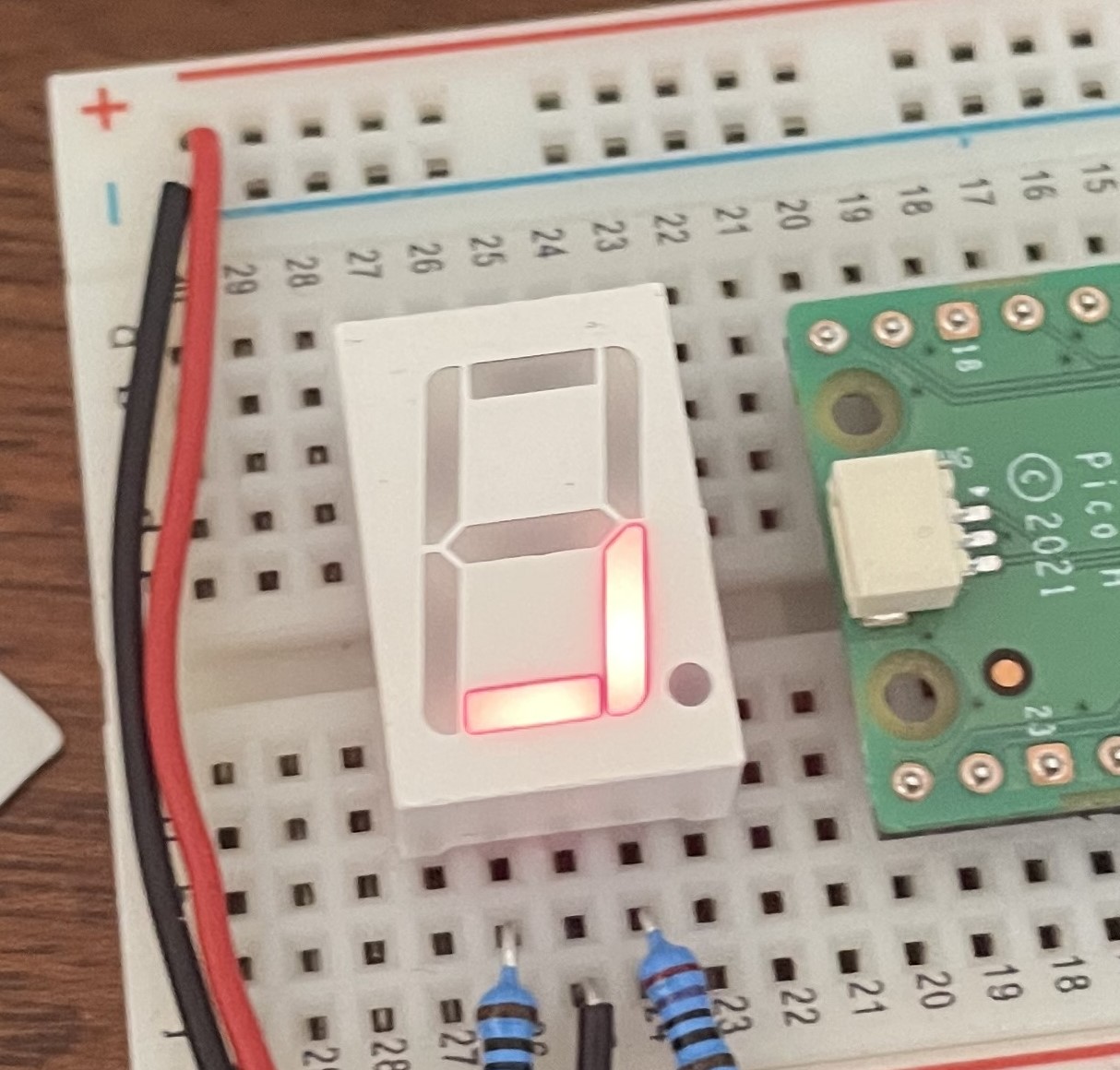
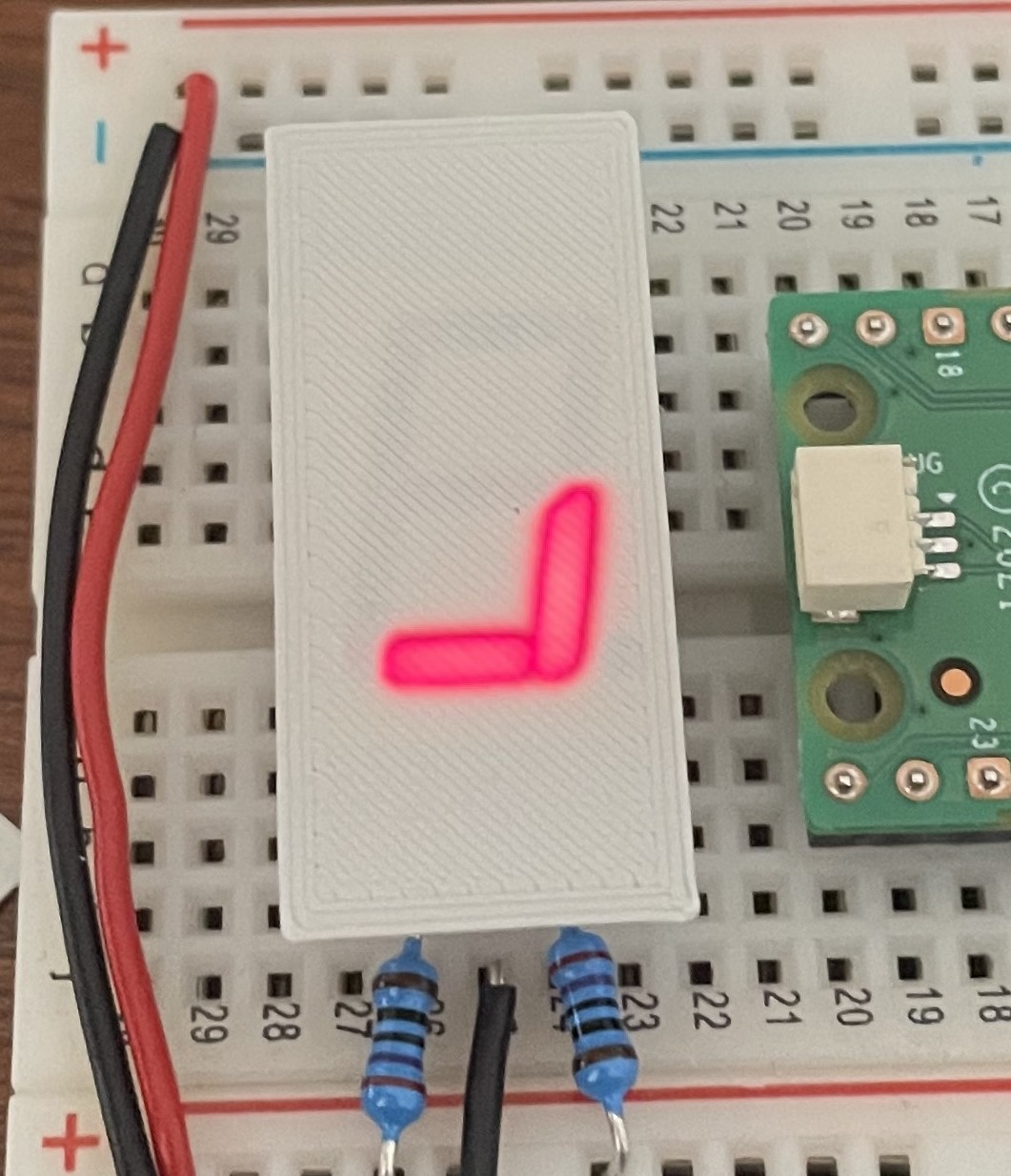
What is this? This is the introductory post in a future series of posts that together will follow the development of a project named Pomoljus. This project log will introduce the Pomoljus from inspiration and early concepts into the more defined concepts.
There will hopefully be a couple future project logs that will follow the continued development of this board throughout the other stages that it will hit.
The Inspiration
The project’s foundation is based upon the Pomodoro Technique[1]. The basics of it is simple; you split your working time into smaller chunks, spaced with short breaks, and after a few work-chunks you get a longer break. The most common version is 25 minutes of work, with a 5 minute break, and a 15 minute break after your third work-chunk. But I know people who prefer longer and shorter variations.
I’ve used this technique throughout university, mostly to get myself through the tougher courses. More accurately I’ve used many shoddy apps (one of my own making) and one surprisingly good hacked together physical timer that a classmate built. It may have been a mess of wires and had a slightly challenging user interface, but it was the most effective studying tool that I’ve found. It’s built using a custom shield for an STM32 Nucleo F401RE[2] development board, and runs on Rust[3].
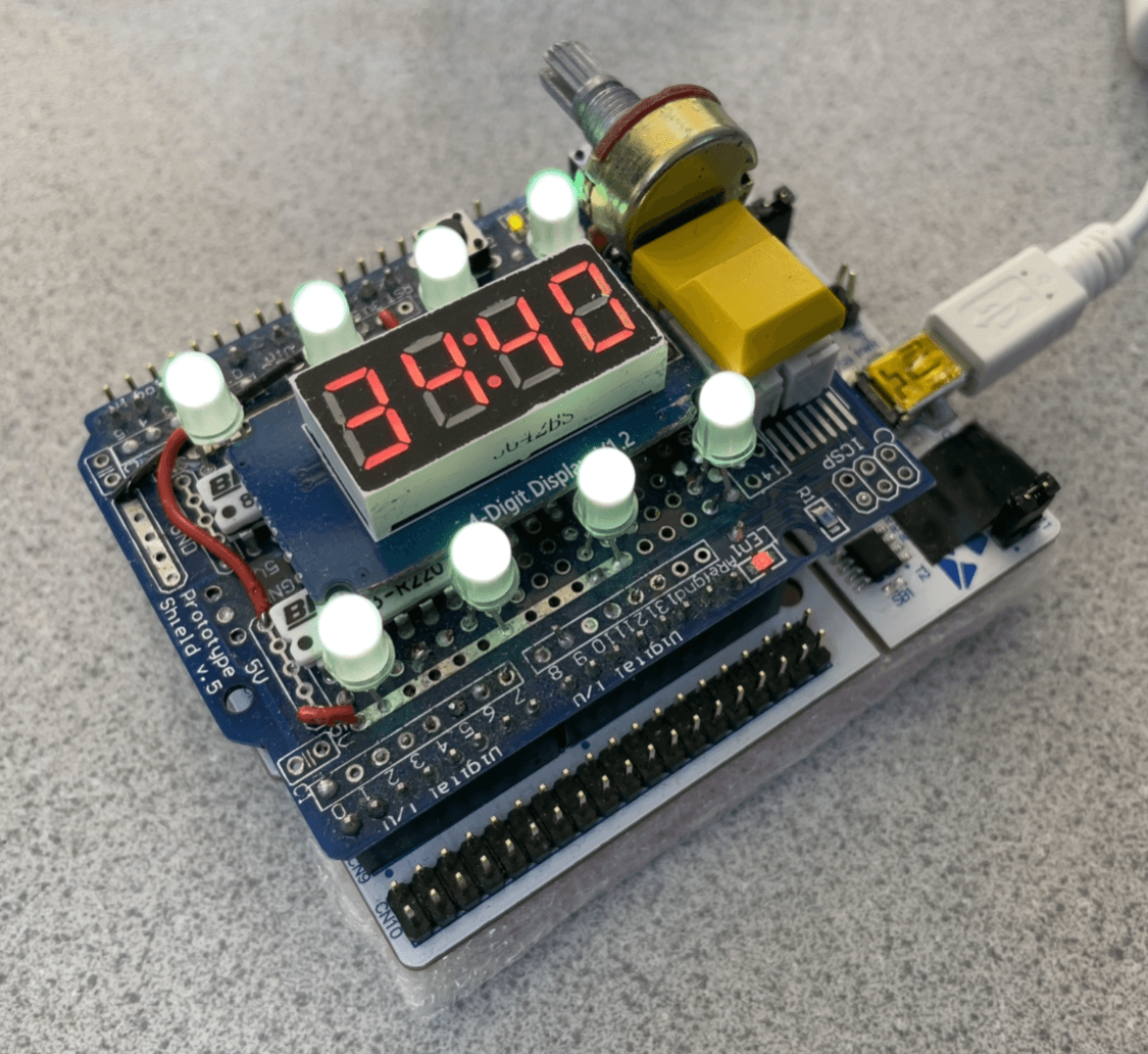
The main idea behind it was the “Library approved” notification method. An array of 8 RGB LEDs sit proudly on top of the device and communicates the state of the clock through different combinations of pulsing colours and brightnesses. In addition to these LEDs was also a 4 digit ”88:88” format 7 segment display. The clock also features two buttons; one for pausing and advancing the progression of the timer sequence, and another for skipping forwards. The two buttons are also used at startup to select one of 3 hardcoded time-chunk presets. But the biggest feature and the reason it resonated so well with me was the aforementioned fact that it notified you using purely visual means. While the clock was running, it showed you this smooth calm animation, while the 7 segment display showed the time left of the current chunk. To minimize distracting flashes it did so without showing the single seconds, instead only showing the remaining tens.
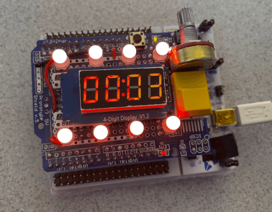
Once you hit zero on the time-chunk you got notified by the lights pulsing in more noticeable colours and patterns, and the 7 segment starts counting up now with the single seconds showing. The result of this is that when the time is up you are not interrupted and forced to stop a loud timer, but instead you notice it when you notice it, and you get shown how far overtime you are. How often are you actually done at the time you said you’d be done? Basically never in my experience. Which is why the ability to snooze the alarm is also an amazing feature. With a click you subdue the lights, but keeps the timer counting up. Then when you’re ready to progress, you progress on to the next time-chunk.
All of this culminated into a prototype so good that I got struck by an irresistible urge to straight up copy the base concepts, with some minor tweaks. I got permission and started working on my own version pretty much right away.
The Concept
I had three areas I wanted to change. The UX, the design, and the hardware components. The core idea of the inspiration would stay the same, but I had enough that I wanted to change that I felt comfortable with calling it my design.
The Design
One of the major things I wanted to change would be the “hackyness” of the design. By both making it smaller and not openly exposing any electronics (even though I think that’s a cool look), I figured it could look less fragile and bomb-like while on your desk. I also wanted to decrease the amount of RGB LEDs, as 8 seemed excessive.
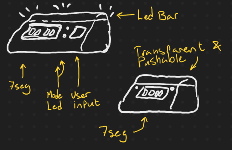
My first design kept the 7 segment display, but focused all of the light to the top of a triangle shape. I quite liked this design, especially if I was able to put the LEDs behind a diffuser so that it looked as if the entire “LED Bar” was one solid light. These designs also featured two additional single color LEDs to act as status lights. I quickly realized the redundancy of them though and removed them. Another thing that got chopped was the button you can see in the first drawing.
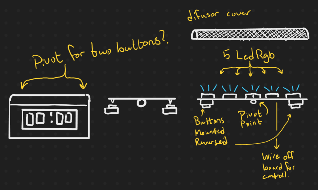
I figured that if I were to condense all the lights into a bar on the top, then that bar would probably need to be of a different material than the rest of the clocks body. So what if that part was loose and could pivot on a central point? Could that be the only piece of user interface? If so then the clock would instantly look pretty damned clean.
Last on the chopping block was the 7segment display. I wouldn’t remove it, but I do think they’re pretty ugly. The empty segments are too bright for the surrounding black-painted face. In a certain light it can be hard to read. I had found an article on Hackaday[4] that showed how you could use car window tint plastic to hide the inactive segments. It was a really good idea, but as I didn’t wanna buy an entire roll of it and I have no car interested friends with any leftovers, I figured I’d do it another way.
By scraping off the black paint from the display, and putting a .2mm layer of PLA over the display, I managed to hide the empty segments almost entirely. Much prettier than having a big black box on the face, especially if I actually end up going with the design from above. Actually completing the design of the Pomoljus is left up to when I make a more final housing for it as the CAD will be an adventure (and project log) of it’s own.
The UX
The navigation of the clock was also something I thought could use some improvement. It’s also a part I thought would be interesting to explore, the limited user interface only being some RGB LEDs and 2 buttons seemed like an interesting challenge. I also tried to make the flow as smooth as possible, which means that I tried to keep the right click as a “normal progression” and the left click as a more settings or “other” options key.
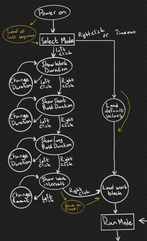
I began by drawing up a state diagram of the Pomoljus from boot to active timer mode. Something I wanted to add was the ability to change your time-chunk settings without needing to re-flash it or access it through some external device. I thought it would be an important aspect to dialing in the chunks to fit the users needs. To avoid being more overwhelming than it already was I limited it to the 4 base components of the timer system, which should still give the user a lot of customizability. By using some of the persistent flash memory of the microcontroller I hope to be able to save these settings and load when you start the device. Which is that perfectly unremarkable feature that makes a device nice to use.
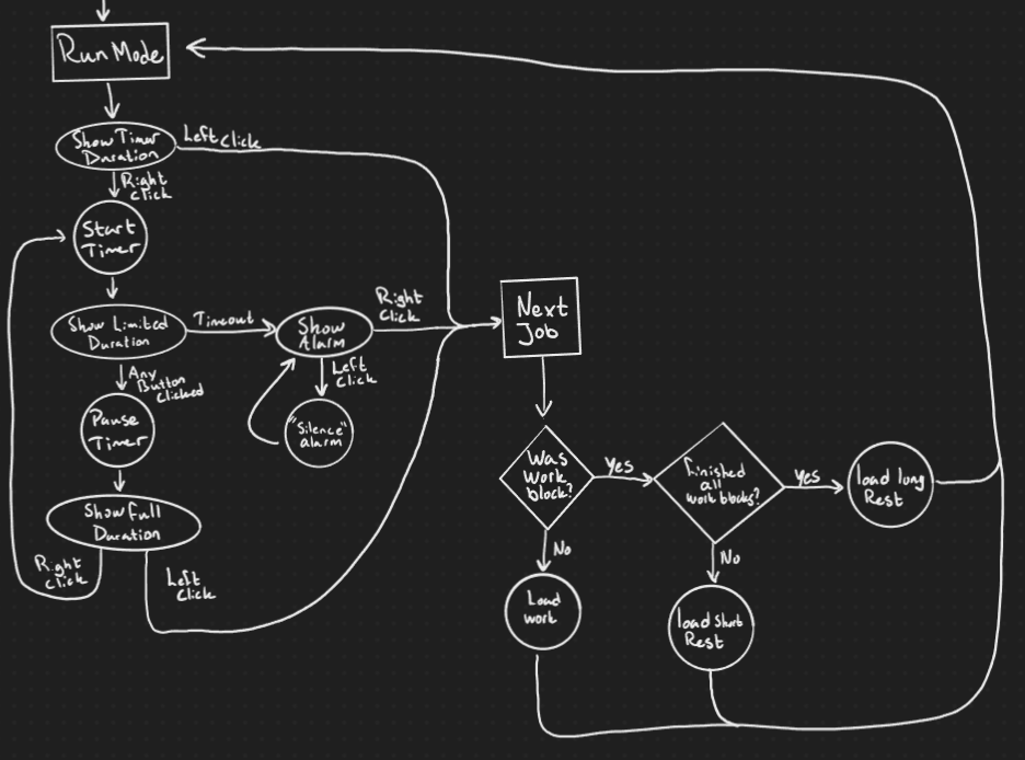
Then its just the part where you actually use the thing left. I wanted to give the user the ability to move through the “UI” without interruption. You still have the ability to pause and snooze the alarm but instead of being in the “middle” of the user flow, it’s instead moved behind a sort of “alternate function” key. A concept that I thought was really smart was the reduction of visual noise, so paused mode and the alarm mode still both show the full second count, while the running timer only shows tens.
Here I also began to toy with the ideas of how to actually show the user what they were doing. For example when skipping a time-chunk, instead of instantly skipping it would require the user to hold the button while the LED bar shifts to red from left to right. Or having a clear color palette for each mode; Greens for work, blues for rest, strong reds for the alarms, and different animation patterns for paused and playing.
In the end, this is something that will have to get carved into stone when I tackle the software. I’m comfortable with getting the state diagram replicated, and saving the settings to flash seems doable. But I’m looking forwards to seeing how I’ll tackle the lights. I’d like to make it work using layers of some kind, and with procedurally generated animations. But I fear that might be unknown territory for me. A problem for another day though, as I still need to get the hardware!
The Hardware
I am not an electrical engineer. I know enough to know I don’t know anything. I could’ve almost certainly selected better components for this, but oh well. Just you wait til the PCB design in the next project log.
In the core, the Pomoljus is a battery driven and portable device. I don’t like single use batteries, and my experience with rechargeable AA batteries has left me wanting more. So I chose a 18650 LiPo battery. For those who don’t know, it’s a popular format of rechargeable batteries that packs quite a bit of power into a pretty compact format. Perfect for my little project. To charge this, I could either try to build my own battery management system, or just get a pre-made off the shelf one. I did the latter and moved on. This would basically guarantee that I could run the Pomoljus off the battery, charge the battery from USB, and run the Pomoljus from the USB while the battery is charging. Which would make it one step above the apple mouse [5].
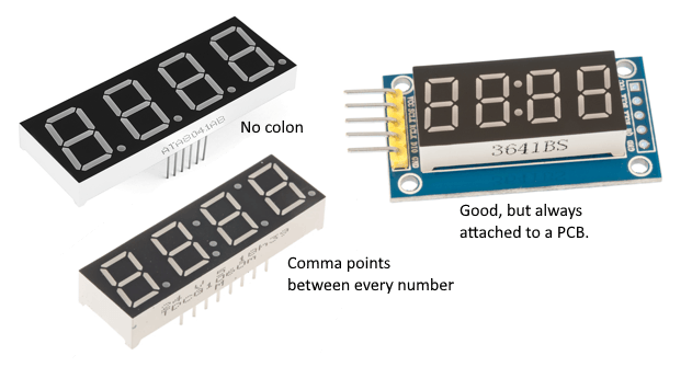
The 7 segment was hard to source, but the classmate from before managed to come in clutch right as I was ready to give up on the entire display. Fun fact, the well known Chinese stores are filled with cheap 4 digit 7 segment displays, but they’re all the same products and they’re all wrong. Do I gain anything on spending sleepless nights searching pages and pages of the same 5 products in the hopes of finding one that is the slight variation that I want? Yes. Yes I actually gain a lot on it and I will not take any questions on the matter.
For the main attraction, the RGB LEDs, I wanted to get some WS2812 serially addressable lights. But as they were basically impossible to get, and I didn’t wanna wait around for them, I instead went for their cousins the KS6812, or more specifically the 3.5x3.5mm SK6812MINIs. Works basically the same, but they’re cheaper and in stock.
For the brain I chose to go with the RP2040, instead of an ARM based chip that I learnt how to use during university, as the RP2040 is cheaper and in stock. They also have quite good specs imo, especially with the dual cores and their PIO shenanigans, which I think will come in handy for this project. I also just wanted to learn how to use a different toolchain than I did for school.
Then I also have some data, in the form of output to the RGB LEDs, and input from the two buttons. An issue with the RP2040 would be the fact that it’s not officially[6] 5V compliant. Which means that I need to level shift both of these data signals. This was harder to find out how to do properly than it was to actually do. Since both data lines are high impedance, meaning there’s no real current draw worth calling home about, you can get away with some pretty simple step-up/down circuits. I’ll go over the details more in the next project log.
What’s next
As of writing this, I have already designed and ordered the second revision of the light bar PCB. I’ll hopefully manage to write the next chapter soon, which will be about my design of the PCB itself. I’ve had some thoughts about the general design too since then, as the battery is much larger than I expected and the 7 segment display much thicker. But that will be a problem for future CAD me… I guess we’ll see.
Lastly, I wanna say thanks for reading along to whatever portion of this you felt like reading. Feel free to reach out to me over at @bpall@mstdn.social
References
- https://francescocirillo.com/products/the-pomodoro-technique
- https://www.st.com/en/evaluation-tools/nucleo-f401re.html
- https://www.rust-lang.org/
- https://hackaday.com/2022/06/03/quick-tip-improves-seven-segment-led-visibility/
- https://www.theverge.com/22967776/apple-magic-mouse-charging-port-bottom-upside-down-its-2022
- https://hackaday.com/2023/04/05/rp2040-and-5v-logic-best-friends-this-fx9000p-confirms/
